 Home Page > KernelCAD Models > Sections > Surface and Solid Sections > 3DS Sections > Surface Patches Home Page > KernelCAD Models > Sections > Surface and Solid Sections > 3DS Sections > Surface Patches
Patches
Surface Patches of Generic 3D
Objects
The simplest surface in DI models is a 3DS patch. A
3DS patch is a
piece of surface between two 3D Curved Segments and
flat edges at top and bottom cross-section planes.

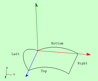
Fig 1. A 3DS patch with one straight (right) and one curved (left) edge.

Fig2. The same patch in wire frame.
A patch has distinct orientation. Figure 2 shows names of each of four edges
in a patch. Left and right edges are considered more important. They are 3D Curved Segments.
Unless we point out specifically, by edges of a patch we normally mean left and
right edges.
Edges can merge at any point or even coincide at whole length.

Fig 3. Patch with edges merged at the top.
frame
Surface of a patch in projection to z-axis is contained exactly
between two sequential base knots. This is the consequence of the fact
that both (left and right ) edges of the patch have ends with z coinciding
with two sequential knots.
In the model from Figure 2 if the second base knot is modified
whole patch will appear expanded or contracted along z-axis.
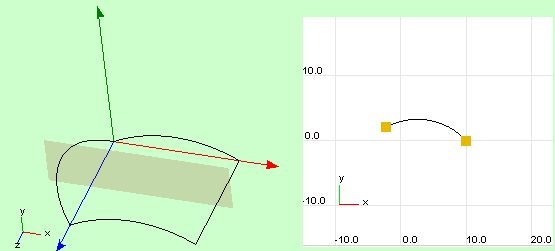
Another assumption about patches in 3DO is that in each cross-section
patch is an arc or straight line.

Fig 3. Patch and its cross-section at the middle z-position.
Modification of curvature if cross-sectional arc (using Cross-section
Editor of 3D Debugger or programmatically) leads to changes of
internal curvature of the surface patch.
There two distinct types of patches: general arc patch similar to one
in Fig
1-3 and linear patch. Cross-line patch is a patch which in any
cross-section is a straight line. Cross-line patch sometimes not quite
correctly is referred to as a flat patch.

Fig 4. Cross-line patch.
In 3D Debugger type of patch can be changed dynamically by using
"Change Class" command of the Cross-section View. Programmatically
it can be achieved using SetType method of
IStripTopol interface. When an arc
patch is converted to Cross-line patch its curvature changed to zero at
every cross--section but edges remain unchanged.
3DS Patches are special kinds of
Generic Patches.
Standard and Radial Arc 3DS Patches
Arc patch has a single parameter,
which determines how curved the patch is. By default this is curvature.
This can be changed to make it radius. Arc patches which have
radius as its parameter are called Radial Patches. Because
radius and curvature are inverse of each other, a radial patch with
constant parameter equal to r is geometrically the same as
standard Arc Patch with curvature 1/r. Despite that, normally
Radial and standard arc patches are different in shape. For
example Radial Arc patch with radius equal 0 at one knot and 1 at
another can not geometrically coincide with any standard arc patch.
Radial patches have restriction that the radius can not change its
sign at whole length of z range. Because of that, standard arc patches
are easier to modify but Radial Patches are more intuitive in many
cases, when modeling standard shapes like cones or spheres.
All patches in a Patch Strip currently must have the same type.
Type of an arc patch can be changed dynamically by using
"Element type" controls on the Current Object page of Modeling
Studio or in Properties dialog (Context menu in Cross-section editor).
|