 Home Page > KernelCAD Models > Sections > Surface and Solid Sections > 3DS Sections > Surfaces and Patch Strips Home Page > KernelCAD Models > Sections > Surface and Solid Sections > 3DS Sections > Surfaces and Patch Strips
Patch Strips
Patch Strips and Surfaces
When base of a Generic 3D Object has more than two knots, surface of the
object consists of Patch Strips. A Patch Strip consist of patches joined by
their top and/or bottom edges.

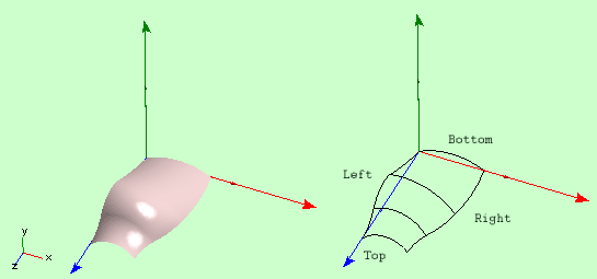
Fig 1. Patch Strip with four base knots.
If not specified otherwise by edge of a Strip Patch we mean either left or
right edges. Edges of a Patch Strip are 3D Curves.
Patch Strips allow forming of more complicated surfaces. Number of
patches in a patch strip can be increased using New Knot command of
3D Debugger. This operation gives more flexibility in approximation
of surface of the real object, which is being modeled.
Two patch strips can have a common edge, in which case they form a Surface.

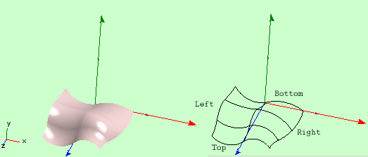
Fig 2. Surface with two Patch Strips and four base knots.
Strictly speaking surface is a strip of patch strips. Surface is the
top of surface modeling hierarchy in the software. Note that a surface
can consist of a single patch strip, which is why sometimes we use
Surface word for separate patch strips too.
Note also that the collection of patch strips, which represent the
surface can consist of a single edge, in which case it will be a
3D Curve,
or have no elements at all. In the later case graphically the
object will be represented only by the local frame of axes.
Left and right edges of a surface can coincide. In this case any
cross-section of the surface is a closed 2D Strip.
We call this type of surfaces closed although it is not correct in
general geometric sense.

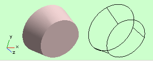
Fig 3. A closed surface with two base knots.
The software can generate additional vertical (orthogonal to z-axis)
patches to cover back and front edges of a closed surface. (Cover Edge
check boxes in the "Current Object">Options ). When these
patches are present, or when all Patch Strips converge at top and Bottom,
the surface is closed in the common geometrical sense. Objects, which
have such a surface appear as Solid Objects in 3D.

Fig 4. Solid Object.
Two vertical patches mentioned here are called Front and Back
Surfaces ( or Top and Bottom Surfaces). The rest of the object surface
is called side surface.
Edges of a patch strip can merge:

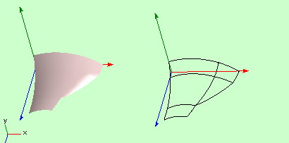
Fig 5. Surface with two patch strips. Edges of one strip co inside between knots 2 and 3.
For a fixed z coordinate cross-section of a patch strip is a two dimensional strip in x and y coordinates. To calculate the 2D strip of the cross-section programmatically: Assuming a reference iStr to IStrip is implemented by a patch strip (It was obtained, for example, via IModel>GetSection()> ISection>IStrip) query iStr>IProfiledElement_KC>IProfiledElement_KC.GetCrossection(z)>IElement>IStripArcLine_KC
|