 Home Page > KernelCAD Models > Sections > Surface and Solid Sections > BRep BSpline objects > Bspline objects Home Page > KernelCAD Models > Sections > Surface and Solid Sections > BRep BSpline objects > Bspline objects
BSpline BRep Objects
BSpline BRep Objects
BSpline BRep 3D Object is the section type created during import of solids via
STEP or IGES formats. It is the most flexible parametric representation of
objects with surfaces.
BSpline BRep objects can also be created programmatically using
IStdShape
Interface obtained via IKO_Model (details) or using Model
Explorer. BSpline BRep objects are also created during various operations like
through (generalised extrusion) operation.
IKO_BRep_Builder
interface allows building BSpline BRep objects from the ground up by defining
geometry of its vertices, edges and faces. See ShapeBuilder class implementation
in Shape Explorer sample for
an example.
Geometry of a BSpline BRep 3D Object (section) is represented by a shape.
Shape has only purely geometric attributes. Most of shapes have sub shapes.
A shape representing BSpline BRep object normally is a shape organised
hierarchically: The top shape is one or several shells. Shells are sets of joned
together faces which often constitute a closed surface.
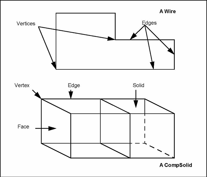
A shell consists of faces (Details). A face is a smooth (not necessarily flat)
piece of surface with several edges. For example a rectangle in 3D is
normally represented by a flat face with four edges. Faces are sub shapes of
shells.
An edge can be either straight or curved, but always smooth curve with two ends.
Ends of an edge may coincide, in which case the curve is closed.
A linked sequence of edges is called a wire. Wires are sub shapes of
faces. Edges are sub shapes of faces and wires.
A vertex, which represents a point with some other non-geometrical additional
information, is the lowest-level sub shape. Ends of edges are vertices. Corners
of a patch are also vertices.
Solid is a shape represented by a single closed shell
Composite solid consist of one or more solids in which some faces can be shared
by adjacent solids (solids with dividing walls inside)
A Compouind shape consists of several grouped, but not necesserily joined,
shapes of different types like solids and edges
Structure of a shape can be discovered at runtime using
IKO_TopExp_Explorer
See also: Shape Explorer Sample
|